Motor Encoder Wiring Diagram
Each of the (20x) orange dots represent a connection that can fail, causing problems for your robot in the middle of a match. Pin number] wiring diagram b a red (3) white (2) blue (1) (4) black (5) yellow (6) green b a pin assignments of pk244pa , pk246pa (6)·····(1) pk244pa and pk246pa are connector type motor.
Arduino Rotary Encoder Wiring

The dealer tells me the encoder motor needs to be replaced.

Motor encoder wiring diagram. Connection wiring diagram • 8 lead wire type black red white brown blue yellow orange green a b a b • 6 lead wire type [( ): As motors, motor starters, contactors, or solenoids. Servo motor wiring diagram sample stepper motor wiring diagram elegant ponent series circuit diagrams.
Helloi would like to see the wiring diagram of this connector. Encoder wiring schemes can be unique to each encoder and one should follow the diagram or pinout designated on the encoder datasheet. This gearmotor is a powerful 12v brushed dc motor with a metal gearbox 37d mm metal gearmotor with 64 cpr encoder (no end cap).
Inside the encoder is a slotted disk connected to the common ground pin c, and two contact pins a and b, as illustrated below. Operating instructions ac motors 21258996 operating instructions moviaxis multi axis servo inverter sew eurodrive brake wiring sew drive calculation diagram toyota celica alternator wiring diagram full version sew. Using a voltmeter, i determined 0 voltage was present on terminal c, (circuit 241, brown wire).
Keep encoder wires as far as possible from high voltage cables and the motor’s field. 01 silverado encoder wiring diagram. Never connect or disconnect the encoder connector or wiring while power is on.
When you turn the knob, a and b come in contact with the common ground pin c, in a particular order according to the direction in which you are turning the knob. Working of ht12e encoder ic gadgetronicx. Doing so may damage the encoder.
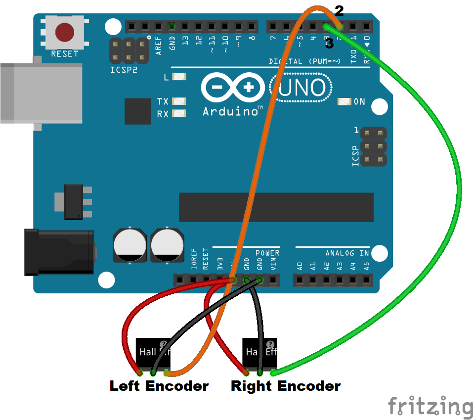
Note that the encoder pin outa needs to be connected to a hardware interrupt pin (digital pin 2 or 3 on an arduino duemilanove or uno). The motor encoder must be mounted securely and restrained from movement. Wiring for a single motor and encoder.
The following diagram depicts the block diagram of an octal to binary encoder. There is an industry standard for resolver wire colors that most the cos and sin circuit will have the same resistance, so the circuit with the. The photodiode array (also called a photosensor) responds by producing a sinusoidal waveform which is
Keep encoder wires as far as possible from high voltage cables and the motor’s field. On/off drivers alternate wiring diagram 4) if wiring hall sensors as encoders , use the encoder 5 v to power the hall sensors. I have searched diagrams for it and it seems like it is hooked up correctly.
The basic construction of an incremental encoder is shown to the right. Front axle motor actuator next. Mg996r servo motor wiring diagram click the image to enlarge it the mg996r is a metal gear servo motor with a maximum stall torque of 11 kg cm.
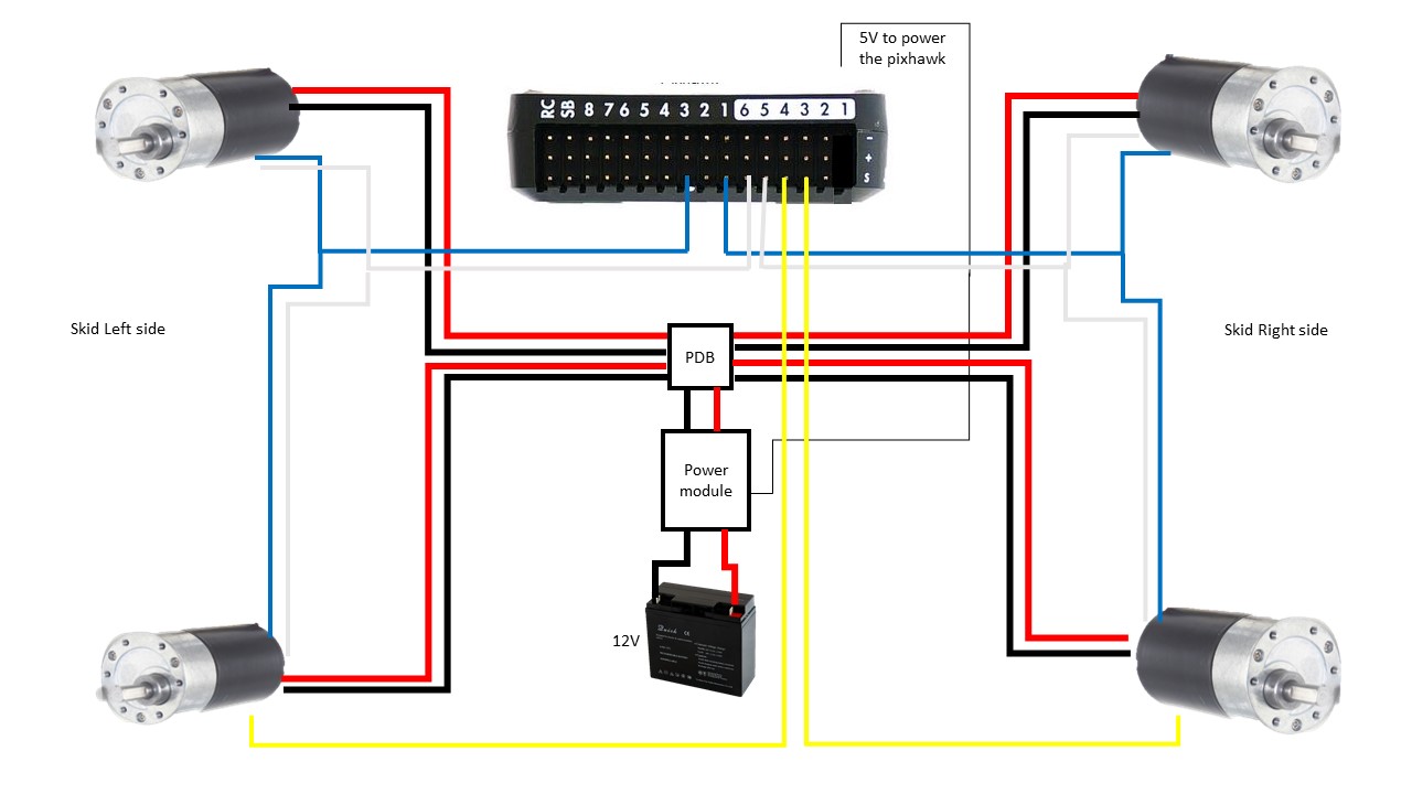
Let’s look at some examples: I have a fanuc at p encoder. The diagram to the left is what it would look like to wire (3x) cim motors and a mag encoder to your robot.
Wiring up the encoders is pretty simple. But other values are also ok. • connect the m12 connector as shown in the wiring diagram.
Ht12e encoder and decoder schematic diagram scientific. The motor encoder must be mounted securely and restrained from movement. I have done a lot of research and have a haynes manual.
1) all wire connections on diagram are pin to pin, not board orientation. The circuit diagram for a 4 to 2 line encoder is shown below octal to binary encoder. It says to put the transfer case in neutral, which i can't electronically have a wiring diagram of the 8 pin connector at the sensor motor i need to.
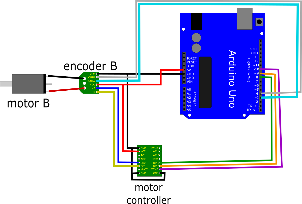
(0.1mh minimum) 2) for best performance select a motor that See the diagram below for details on wiring up the encoder for motor b, and repeat for motor a. I cannot find a lot of information about the output voltage.
The diagram below shows the dimensions (in mm) of the 37d mm line of this header works with standard ″ male headers and our male jumper and precrimped wires. Does anyone have the wiring diagram for a fanuc 5m servo motor encoder. Mabuchi motor encoder dc 12 volt wiring diagram.
These or gates encode the eight inputs with three bits. The circuit can be suitably modified to get pulses of sufficient length. 3) typically a motor that has an inductance of around 1mh and a resistance of around 1 ohm works well.
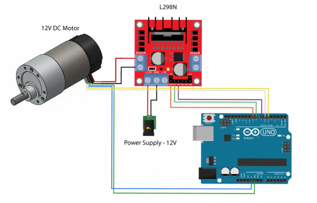
A beam of light emitted from an led passes through a transparent disk patterned with opaque lines, and is picked up by a photodiode array. 2 wires to power the motor (often labeled as : The dc motor with encoder has 6 wires :
M1, m2 , motor power.) 2 wires to power the encoder (often labeled gnd and 3.3v) 2 wires to send signal of position to the microcontroller (arduino) (labeled as encoder output or c1 & c2) first you will connect 2 wires to power the encoder. I chose this wire based on the wiring diagram, which showed fuse 24 in the ip fuse box feeding voltage to the front axle motor. Normal_tcem the dealer tells me the encoder.
Going this far without first checking the fuse could turn out to be pretty embarrassing if the Logical expression for a1 and a0. My problem is that when this was removed from service the wire was cut off and i have no.

InDepth How Rotary Encoder Works and Interface It with Arduino
Feedback connections Nix

Help Wiring brushless motor with building encoder Miscellaneous ArduPilot Discourse

Motor Encoder Wiring
BMB6202/032S2/UA002A SKF Motor Encoder Unit (Motor Speed Sensor), 6202/VK2415


Motor Encoder Wiring
Wiring Diagrams(WISE) WEIHONG DOC

How to test motor encoder with Arduino «

Como usar motor DC com encoder no Arduino Arduino e Cia
Solved Given The Schematic Of A DC Motor With Encoder Con...
Wiring the encoders with Arduino ESP8266 Robotics Projects
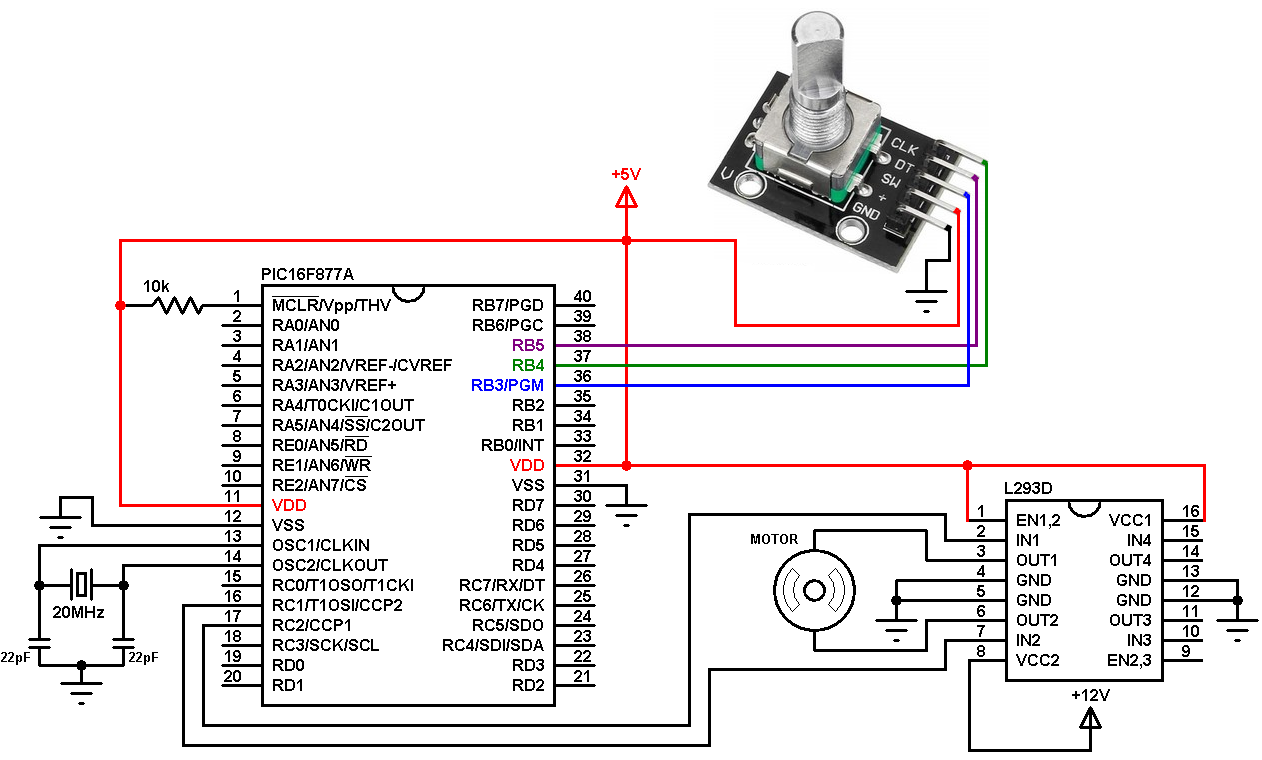
DC Motor speed/direction control using PIC16F877A and rotary encoder
Simple Motor Optical Encoder Schematic PyroElectro News, Projects & Tutorials

Rotary Encoder Arduino Wiring

Quadrature encoder signal from dc motor is very noisy Robotics Stack Exchange

Motor With Encoder, How to Read Input Value From Encoder 3 Steps (with Pictures) Instructables
US Digital® Products MD2S Microstepping Motor Driver
Motor Encoders with Arduino Bot BlogBot Blog
Motor Encoder Wiring
