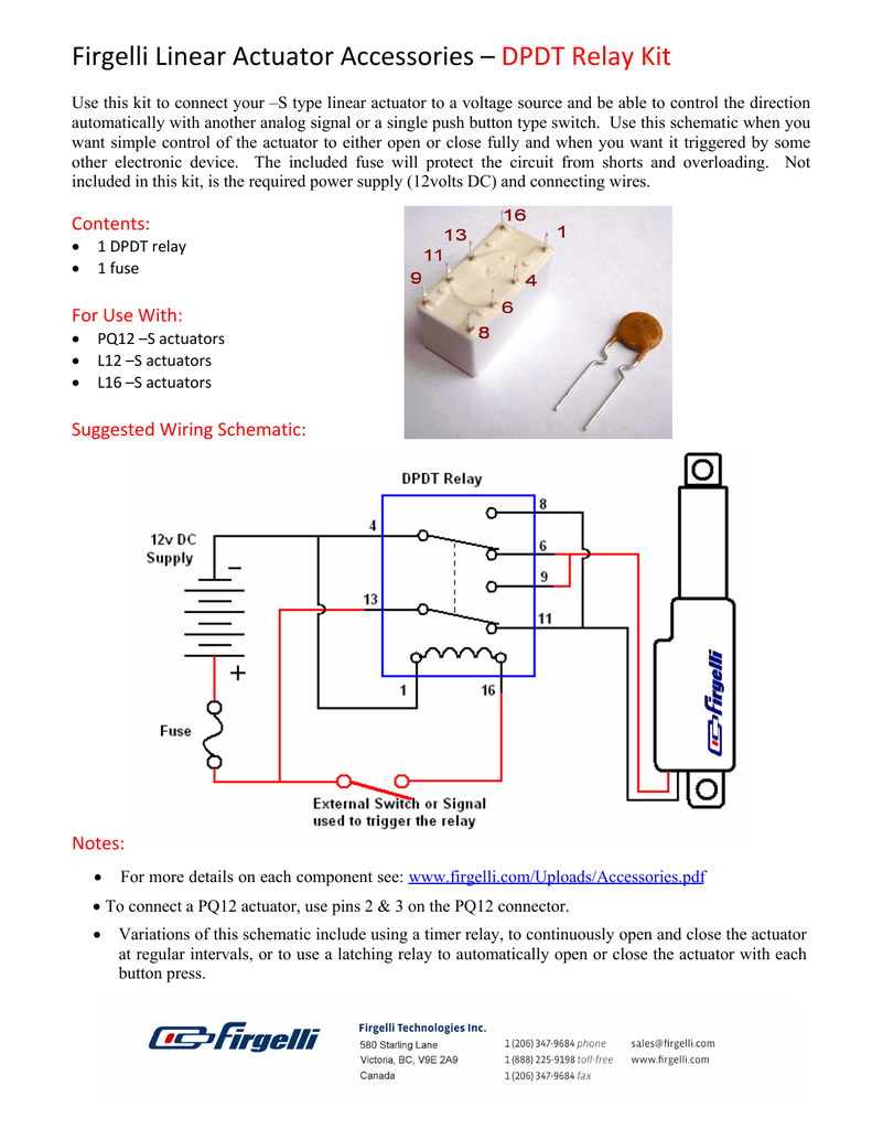
Actuator Wiring Diagram

Vt Commodore Ignition Wiring Diagram, Complete Wiring Diagrams For Holden Commodore VT, VX, VY, VZ, VE, VF, 5.36 MB, 03:54, 32,796, John Amahle, 2018-08-01T19:37:41.000000Z, 19, Vt Commodore Ignition Wiring Diagram, to-ja-to-ty-to-my-to-nasz-swiat.blogspot.com, 1272 x 1800, jpeg, bcm pcm 12j swiat nasz, 20, vt-commodore-ignition-wiring-diagram, Anime Arts
That actuator does not have a listing of the current draw, either. So what is needed is to locate an actuator with built in limit switches to stop it at each end of the stroke. Then this project may have a hope of working. Connection wiring (wire numbers 17, 17a, 18 or 18a per electrical wiring diagrams figures 1 and 2 on page 4 and 5).
Do not hammer or gouge the outside surface of the extension rod. This may damage the plating integrity or cause surface irregularities which can A wiring diagram is a straightforward visual representation from the physical connections and physical layout of an electrical system or circuit. It shows how the electrical wires are interconnected and will also show where fixtures and. A wiring diagram is an easy visual representation of the physical connections and physical layout of the electrical system or circuit. It shows what sort of electrical wires are interconnected which enable it to also show where fixtures and components could possibly be connected to the system. Door lock actuator wiring diagram. Print the electrical wiring diagram off plus use highlighters to be able to trace the signal. When you use your finger or the actual circuit with your eyes, it may be easy to mistrace the circuit.
Dresser Rcs Actuator Wiring Diagram

Linak Actuator Wiring Diagram Sample

How to Wire Up a Linear Actuator to a Rocker Switch - 12V Actuators

Wiring Diagram For Actuator

Wiring Diagram for Linear Actuator - MyTractorForum.com - The Friendliest Tractor Forum and Best
Actuator Control with External Limit Switch - Progressive Automations – Progressive Automations

12v Linear Actuator Wiring Diagram - Wiring Diagram Schemas

Linear Actuator Relay Wiring Diagram - Wiring Diagram Schemas

Eim Actuator Wiring Diagram | Free Wiring Diagram

Linear Actuator Wiring
