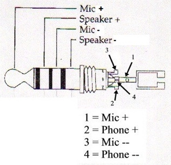
Aircraft Headset Wiring Diagram

Vt Commodore Ignition Wiring Diagram, Complete Wiring Diagrams For Holden Commodore VT, VX, VY, VZ, VE, VF, 5.36 MB, 03:54, 32,796, John Amahle, 2018-08-01T19:37:41.000000Z, 19, Vt Commodore Ignition Wiring Diagram, to-ja-to-ty-to-my-to-nasz-swiat.blogspot.com, 1272 x 1800, jpeg, bcm pcm 12j swiat nasz, 20, vt-commodore-ignition-wiring-diagram, Anime Arts
Recognizing aircraft sounds with the headset’s active and passive noise reduction, typical aircraft sounds (such as engines, propellers, warning alarms, and other sound sources) may not sound familiar. We strongly advise you to make sure you can hear and recognize these sounds when using the bose® a20® aviation headset while operating any. Five different configurations are shown below. Determine which figure best describes your headset, and install the modules according to.
Jack wiring aircraft plug microphone aeroelectric connection tip ring input intercom articles bass three connect mj2 ground freestompboxes solder dynon. Headphone headphones poke slashgear pinout. Aviation headset jack wiring diagram. 3] connector & contact selection david clark. Plug is 5 23mm or 0 206 general aviation headphone plug this is a readily available 6 35mm mono or stereo plug the mating shaft of the plug is 6 35mm or 0 250. ( 1 per headset ) (11) white / orange to to pin 11 headphone audio trig ty 91 headphone jack. This installation diagram is for a single radio system without audio panel. The radio circuit based on transistor 2n918 and diode 1n82 receives in the 220mhz to 400mhz range. Capacitor c1 and inductor l1 forms the tank circuit for tuning.
Wheels, Wings and Radio Things: Wiring Up an Aviation Headset Adapter for ICA21

New Aircraft Headset Wiring Diagram #diagram #diagramtemplate #diagramsample

Aviation Headset Jack Wiring Diagram : Rt 7814 Clark Headset Wiring Diagram On David Clark
New Aircraft Headset Wiring Diagram #diagram #diagramtemplate #diagramsample | Stereo headphones

New Aircraft Headset Wiring Diagram #diagram #diagramtemplate #diagramsample

Aviation Headset Jack Wiring Diagram - Plug In Aviation Headset To Personal Computer Ninertwo

New Aircraft Headset Wiring Diagram #diagram #diagramtemplate #diagramsample

Bose Aviation Headset Wiring Diagram - Wiring Diagram

Aircraft Headset Wiring Diagram - Wiring Diagram
