Car Amp Meter Wiring Diagram
Vt Commodore Ignition Wiring Diagram, Complete Wiring Diagrams For Holden Commodore VT, VX, VY, VZ, VE, VF, 5.36 MB, 03:54, 32,796, John Amahle, 2018-08-01T19:37:41.000000Z, 19, Vt Commodore Ignition Wiring Diagram, to-ja-to-ty-to-my-to-nasz-swiat.blogspot.com, 1272 x 1800, jpeg, bcm pcm 12j swiat nasz, 20, vt-commodore-ignition-wiring-diagram, Anime Arts
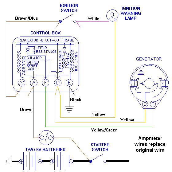
Digital volt amp meter connection diagram ammeter blues or electrics for dummies access norton panelmeter voltmeter 4 5 30v 10a panelmeters jsumo com wiring boat design net using pic microcontroller why is an always connected in series and a parallel circuit quora connecting car with alternator transducer meters wire by type instruments displays cers. Wiring for ammeter or voltmeter. A short description of how to wire in an ammeter or voltmeter for your car from someone who understands the principles. The ammeter shows direction and rate of current to and from the battery.
Digital amp meter wiring diagram from i. ytimg. com to properly read a wiring diagram, one offers to learn how the particular components within the system operate. For example , when a module is powered up and it sends out the signal of 50 percent the voltage and the technician would not know this, he would think he has a problem, as this individual would expect a new 12v signal. Please read these instructions carefully before installing. All instructions refer to viewing from the rear. Disconnect battery ground cable. Connect an 8 awg (10. 0 mm. 2) wire, minimum, with an insulation temperature rating of 220° f (105° c), minimum, from the battery terminal 3s wiring diagram 1 ph, 2 wire (1 pt, 1 ct) glems would like to thank and acknowledge the use of the following meter connection diagrams from dr. Be aware that these are general diagrams using standard test switches which may not match some utility standards in their configuration and are for reference only.
Ammeter wiring CJ2A - The CJ2A Page Forums
I want to wire in an ammeter to a 12v landrover

Digital Volt Amp Meter Wiring Diagram Gallery

In-car Amp meter

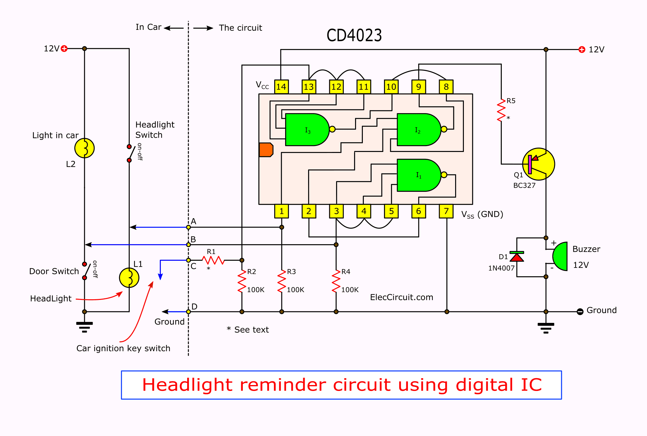
Amp meter for CAR | ElecCircuit.com

12 Gauge Wire, Amp Simple Auto Meter Water Temp Gauge Wiring Diagram Trusted Wiring Diagrams

12 Volt Amp Meter Wiring Diagram - easywiring

Ammeter Wiring Diagram

Car Amp Meter Wiring Diagram
