Brushless Generator Wiring Diagram

Vt Commodore Ignition Wiring Diagram, Complete Wiring Diagrams For Holden Commodore VT, VX, VY, VZ, VE, VF, 5.36 MB, 03:54, 32,796, John Amahle, 2018-08-01T19:37:41.000000Z, 19, Vt Commodore Ignition Wiring Diagram, to-ja-to-ty-to-my-to-nasz-swiat.blogspot.com, 1272 x 1800, jpeg, bcm pcm 12j swiat nasz, 20, vt-commodore-ignition-wiring-diagram, Anime Arts
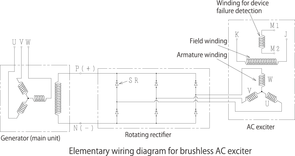
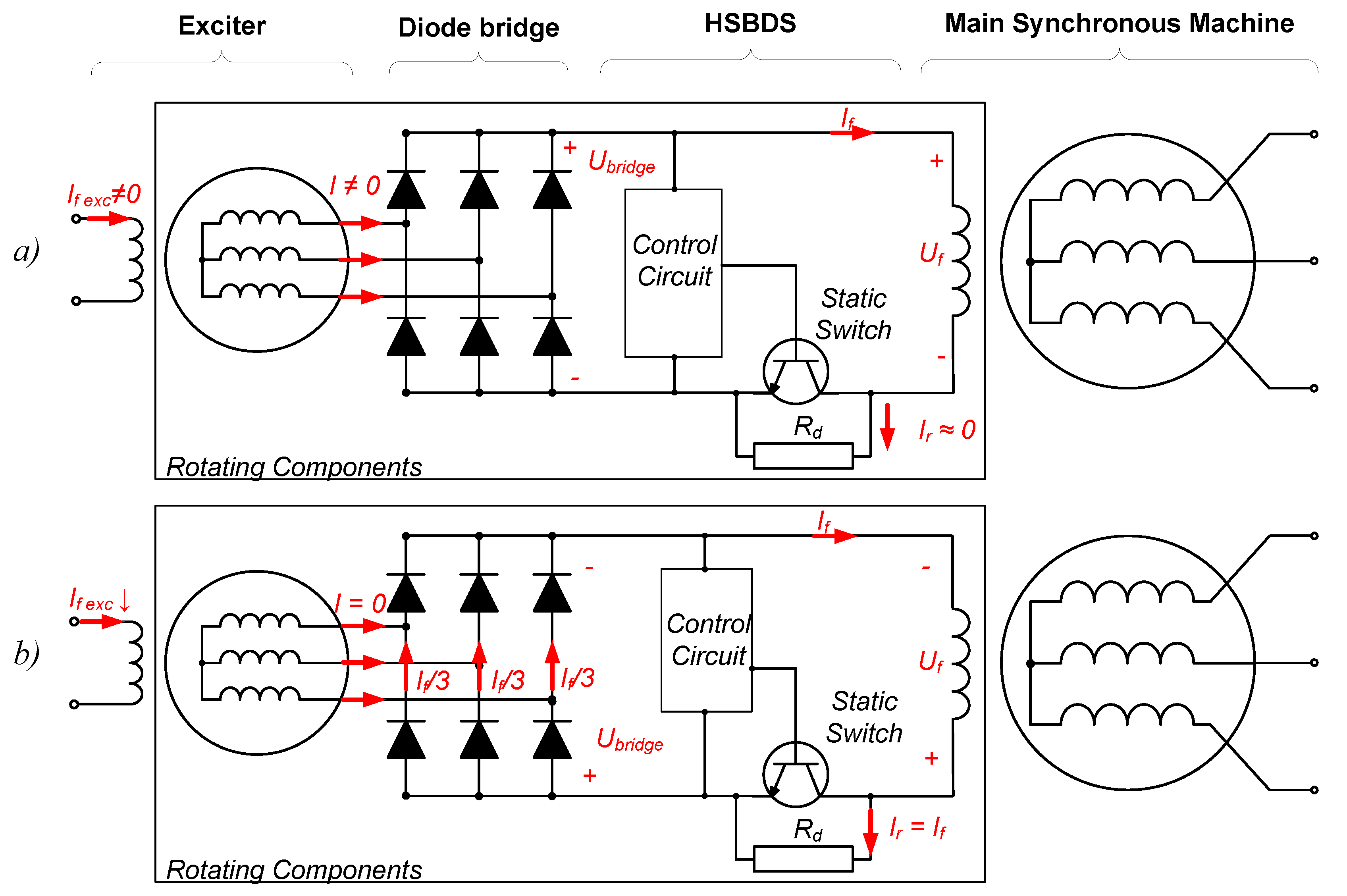
Brushless vs brushed dc motors when and why to choose one over the other article mps sensored single phase bldc motor driver using pic16f1613 generator excitation. Small sel generators wiring diagrams user manual connection diagram of the single phase induction generator scientific te20 and alternator how to work with sd controller set china avr. Efforts were focused on eliminating the brush arrangement and led to the advent of a brushless generator. This independent source can be an auxiliary winding on the stator or.
Bldc motor construction motors brushless dc working electric generator magnet induction permanent stator rotor phase principle. Magnaplus® generators are brushless, self excited, externally voltage regulated, synchronous. Brushless generator wiring diagram the generator's data plate gives the voltage, current and frequency rating of the generator. The larger one produces power as described above. Wiring diagram of brushless motor driver. Brushless generator wiring diagram wiring diagram. 14 mm2 mm2 code wire color b l br g gr v p black blue brown green gray violet pink r w y lb lg o red white yellow light. A brushless capacitor excited alternator includes a rotor assembly having a coil and a diode connected in series with the coil. A stator contains the output coil of the alternator.
Single Phase Brushless Generator Wiring Diagram - Wiring Diagram and Schematic

Brushless Alternator Wiring Diagram. Internal Connection of Brushless Generator, Revolving field

Wiring Diagram For Brushless Generator - Wiring23

Wiring Diagram Of Brushless Generator

Wiring Diagram Of Brushless Generator

Brushless Generator Exciter Diagram - Diagram Media

Wiring Diagram For Brushless Generator - Wiring23

How Does Brushless Alternator Works? (With Diagram) | Marinesite

Brushless DC Motor - Construction, Working Principle and Advantages
